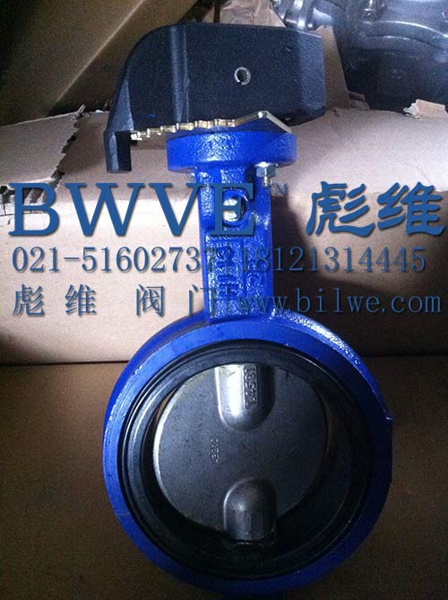
Center Line弹性衬胶蝶阀 软密封衬胶蝶阀具有优秀的设计特点和结构材料,在多种应用中为苛刻磨蚀性和磨蚀性工况提供可重复的紧密关闭性能。
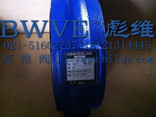
尺寸: 1½ - 56" (DN 40-1400)
等级: 150 (PN 10-16)
温度: 14° to +300°F (-10° to +149°C)
面间距尺寸: 全部为短型结构
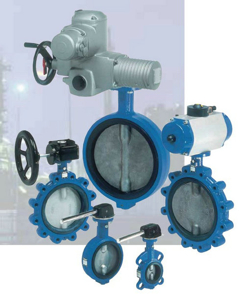
阀体型式: 对夹式/带对中支耳、对夹式、支耳式、法兰式
| Center Line Resilient Seated Butterfly Valves |
|---|
| Series 200 | | Series 225-250 |
|

Series 200 Dimensions 2" - 30" Wafer & Lug
For installation and maintenance instructions, please refer to the IOM manual. |
|---|
| Inches / mm | A | B | C | D | E | F | G | H | J |
|---|
2"
50 | 6 3/8
161.93 | 3 3/16
80.96 | 1 7/8
47.63 | 1 1/4
31.75 | 1/2
12.70 | 3/8
9.53 | 2.76
70 | 0.39
10 | 2 3⁄4
69.85 | 2 1/2"
65 | 6 7/8
174.63 | 3 1/2
88.90 | 2
50.80 | 1 1/4
31.75 | 1/2
12.70 | 3/8
9.53 | 2.76
70 | 0.39
10 | 2 3⁄4
69.85 | 3"
80 | 7 1/8
180.98 | 3 3/4
95.25 | 2
50.80 | 1 1/4
31.75 | 1/2
12.70 | 3/8
9.53 | 2.76
70 | 0.39
10 | 2 3⁄4
69.85 | 4"
100 | 7 7/8
200.03 | 4 1/2
114.30 | 2 1/8
53.98 | 1 1/4
31.75 | 5/8
15.88 | 3/8
9.53 | 2.76
70 | 0.47
12 | 2 3⁄4
69.85 | 5"
125 | 8 3/8
212.73 | 5
127.00 | 2 3/8
60.33 | 1 1/4
31.75 | 3/4
19.05 | 3/8
9.53 | 2.76
70 | 0.55
14 | 2 3⁄4
69.85 | 6"
150 | 8 7/8
225.43 | 5 1/2
139.70 | 2 3/8
60.33 | 1 1/4
31.75 | 3/4
19.05 | 3/8
9.53 | 2.76
70 | 0.55
14 | 2 3⁄4
69.85 | 8"
200 | 10 1/4
260.35 | 6 7/8
174.63 | 2 1/2
63.50 | 1 3/4
44.45 | 7/8
22.23 | 7/16
11.11 | 4.02
102 | 0.67
17 | 3 3/4
95.33 | 10"
250 | 11 1/2
292.10 | 8
203.20 | 2 3/4
69.85 | 1 3/4
44.45 | 1 1/8
28.58 | 7/16
11.11 | 4.02
102 | 0.87
22 | 3 3/4
95.33 | 12"
300 | 13 1/4
336.55 | 9 5/8
244.48 | 3 1/8
79.38 | 1 3/4
44.45 | 1 1/4
31.75 | 7/16
11.11 | 4.02
102 | 0.95
24 | 3 3/4
95.33 | 14"
350 | 14 1/2
368.30 | 10 1/2
266.70 | 3 1/8
79.38 | 1 3/4
44.45 | 1 1/4
31.75 | 7/16
11.11 | 4.02
102 | 0.95
24 | 3 3/4
95.33 | 16"
400 | 15 3/4
400.05 | 12 7/8
327.02 | 3 1/2
88.90 | 2
50.80 | 1 5/16
33.34 | 7/8
22.23 | 6.50
165 | 1.06
27 | 6 1/2
165.10 | 18"
450 | 16 5/8
422.28 | 13 5/8
346.08 | 4 1/4
107.95 | 2
50.80 | 1 1/2
38.10 | 7/8
22.23 | 6.50
165 | 1.06
27 | 6 1/2
165.10 | 20"
500 | 18 7/8
479.43 | 15 1/8
384.18 | 5 3/8
136.53 | 2 3/4
63.50 | 1 5/8
41.28 | 7/8
22.23 | 6.50
165 | 1.26
32 | 6 1/2
165.10 | 24"
600 | 22 1/8
561.98 | 18 3/8
466.73 | 6 1/8
155.58 | 2 3/4
69.85 | 2
50.80 | 7/8
22.23 | 6.50
165 | 1.42
36 | 6 1/2
165.10 | 30"
750 | 25 1/2
647.70 | 24 3/4
628.65 | 6 3/4
171.45 | 3 1/4
82.55 | 2 1/2
63.50 | 7/8
22.23 | 8 1/2
215.90 | N/A | 11 1/4
285.75 |
Dimensions 2" - 30" Wafer & Lug
For installation and maintenance instructions, please refer to the IOM manual. |
|---|
| Inches / mm | K | L1 | L2 | M1 | M2 | N | O | P |
|---|
2"
50 | 4 3⁄4
120.65 | 5⁄8-11 | 11⁄16
17.46 | 4 | 4 | 4
101.60 | 1.26
32.0 | Woodruff #3 | 2 1/2"
65 | 5 1⁄2
139.70 | 5⁄8-11 | 11⁄16
17.46 | 4 | 4 | 4 3⁄4
120.65 | 1.83
46.5 | Woodruff #3 | 3"
80 | 6
152.40 | 5⁄8-11 | 11⁄16
17.46 | 4 | 4 | 5
127.00 | 2.54
64.5 | Woodruff #3 | 4"
100 | 7 1/2
190.50 | 5⁄8-11 | 11⁄16
17.46 | 8 | 4 | 6 1/4
158.75 | 3.54
89.9 | Woodruff #9 | 5"
125 | 8 1/2
215.90 | 3⁄4-10 | 13/16
20.64 | 8 | 4 | 7 1/2
190.50 | 4.36
110.7 | Woodruff #9 | 6"
150 | 9 1/2
241.30 | 3⁄4-10 | 13/16
20.64 | 8 | 4 | 8 3/8
212.73 | 5.72
145.3 | Woodruff #9 | 8"
200 | 11 3/4
298.45 | 3⁄4-10 | 13/16
20.64 | 8 | 4 | 10 5/8
269.88 | 7.6
193.0 | Woodruff #9 | 10"
250 | 14 1/4
361.95 | 7⁄8-9 | 15/16
23.81 | 12 | 4 | 12 7/8
327.03 | 9.5
241.3 | Woodruff #15 | 12"
300 | 17
431.80 | 7⁄8-9 | 15/16
23.81 | 12 | 4 | 15 7/8
403.23 | 11.45
290.8 | Woodruff #15 | 14"
350 | 18 3/4
476.25 | 1-8 | 1 1/16
26.99 | 12 | 4 | 17 1/8
434.98 | 12.78
324.6 | Woodruff #15 | 16"
400 | 21 1/4
539.75 | 1-8 | 1 1/16
26.99 | 16 | 4 | 19 1/4
488.95 | 14.97
380.2 | 5⁄16" Sq. x 1 3/4" | 18"
450 | 22 3/4
577.85 | 11/8 - 7 | 1 1/4
31.75 | 16 | 4 | 21 1/4
539.75 | 16.83
427.5 | 3⁄8" Sq. x 1 1⁄2" | 20"
500 | 25
635.00 | 11/8 - 7 | 1 1/4
31.75 | 20 | 4 | 23 5/8
650.88 | 18.67
474.2 | 3⁄8" Sq. x 1 3⁄4" | 24"
600 | 29 1/2
749.30 | 11/4 - 7 | 1 3/8
34.93 | 20 | 4 | 27 7/8
708.03 | 22.62
574.5 | 1⁄2" Sq. x 2 1⁄4" | 30"
750 | 36
914.40 | 11/4 - 7 | 1 1/4
31.75 | 28 | 4 | 34 3/8
873.13 | 28.6
726.4 | 5⁄8" Sq. x 2 5⁄8" |
L1 and M1 refer to Lug style valves, L2 and M2 refer to Wafer Style. “C” dimension is listed with elastomer in the relaxed condition. Approximately 1/8" Total compression is required for proper sealing with pipe flanges. Valves are designed for installation between ASME B16.1 Class 125 (Iron) and B16.5 Class 150 (Steel) flanges. Gaskets are not needed, and should not be used since the seat face seals against the mating flange. If the valve is to be installed in between any other flanges, consult your Center Line agent or the factory for additional information. Center Line recommends that a blind flange be used on end of line applications.
“O” dimension is the valve clearance dimension.
*Dimensions 28" - 48" Double Flanged
For installation and maintenance instructions, please refer to the IOM Manual. |
|---|
|
| A | B | C | D | E | F | G | H | J |
|---|
| 28 | in | 24.6 | 20.5 | 6.6 | 3.7 | 2.2 | 0.7 | 10 | 2.5 | 24 | | mm | 626 | 521 | 165 | 95 | 54 | 18 | 254 | 63.4 | 24 | | 30 | in | 26 | 21.8 | 6.7 | 3.7 | 2.2 | 0.7 | 10 | 2.5 | 24 | | mm | 660 | 554 | 167 | 95 | 54 | 18 | 254 | 63.4 | 24 | | 32 | in | 26.2 | 23.3 | 7.6 | 3.7 | 2.4 | 0.7 | 10 | 2.5 | 24 | | mm | 666 | 591 | 190 | 95 | 60.3 | 18 | 254 | 63.4 | 24 | | 36 | in | 28.4 | 25.6 | 8.1 | 5.1 | 2.4 | 0.7 | 10 | 3 | 28 | | mm | 722 | 650 | 203 | 130 | 60.3 | 18 | 254 | 75 | 28 | | 40 | in | 31.7 | 28.1 | 8.7 | 5.1 | 2.4 | 0.7 | 10 | 3.3 | 32 | | mm | 806 | 713 | 218 | 130 | 60.3 | 18 | 254 | 85 | 32 | | 42 | in | 34.1 | 30.3 | 10 | 5.9 | 2.6 | 0.7 | 10 | 3.3 | 32 | | mm | 865 | 770 | 251 | 150 | 66 | 18 | 254 | 85 | 32 | | 48 | in | 36.9 | 33.7 | 10.9 | 5.9 | 2.8 | 0.9 | 11.7 | 4.1 | 40 | | mm | 938 | 855 | 276.4 | 150 | 70 | 22 | 298 | 105 | 40 |
*Dimensions 28" - 48" Double Flanged
For installation and maintenance instructions, please refer to the IOM Manual. |
|---|
|
| K | L | M | N | P | Q | R | S |
|---|
| 28 | in | 1.4 | 34 | 0.7 Sq. | 36.6 | 27.8 | 11.8 | 1.25 - 7 | 1.3 | | mm | 35 | 863.4 | 18 Sq. | 930 | 695 | 300 | – | 33 | | 30 | in | 1.4 | 36 | 0.7 Sq. | 39.4 | 29.8 | 11.8 | 1.25 - 7 | 1.3 | | mm | 35 | 914.4 | 18 Sq. | 984 | 744 | 300 | – | 33 | | 32 | in | 1.6 | 39.5 | 0.7 Sq. | 42.4 | 31.8 | 11.8 | 1.5 - 6 | 1.3 | | mm | 41.3 | 978 | 18 Sq. | 1060 | 795 | 300 | – | 33 | | 36 | in | 1.6 | 42.75 | 0.8 Sq. | 47 | 34 | 11.8 | 1.5 - 6 | 1.3 | | mm | 41.3 | 1086 | 20 Sq. | 1169 | 864.7 | 300 | – | 33 | | 40 | in | 1.6 | 47.25 | 0.9 Sq. | 51.6 | 38.6 | 11.8 | 1.5 - 6 | 1.5 | | mm | 41.3 | 1200 | 22 Sq. | 1289 | 965 | 300 | – | 38 | | 42 | in | 1.6 | 49.5 | 0.9 Sq. | 53 | 40.5 | 11.8 | 1.5 - 6 | 1.4 | | mm | 41.3 | 1257 | 22 Sq. | 1346 | 1030 | 300 | – | 35 | | 48 | in | 1.6 | 56 | 1.1 Sq. | 59.5 | 45.7 | 13.8 | 1.5 - 6 | 1.5 | | mm | 41.3 | 1422 | 28 Sq. | 1511 | 1160 | 350 | – | 38 |
* Please note that dimensions apply to standard product only.
| Weights 2" - 48" - lbs (kg) |
|---|
| 2" | 2½" | 3" | 4" | 5" | 6" | 8" | 10" | 12" | 14" | 16" |
|---|
| Wafer | 6 | 7 | 10 | 13 | 18 | 20 | 32 | 42 | 70 | 95 | 117 | | -2.7 | -3.2 | -4.5 | -5.9 | -8.2 | -9.1 | -14.5 | -19.1 | -31.7 | -43.1 | -53.1 | | Lug | 7 | 8 | 14 | 26 | 28 | 31 | 49 | 72 | 105 | 155 | 195 | | -3.2 | -3.6 | -6.4 | -11.8 | -12.7 | -14.1 | -22.2 | -32.7 | -47.6 | -70.3 | -88.5 | | Flanged | – | – | – | – | – | – | – | – | – | – | – | | – | – | – | – | – | – | – | – | – | – | – |
| Weights 2" - 48" - lbs (kg) |
|---|
| 18" | 20" | 24" | 28" | 30" | 32" | 36" | 40" | 42" | 48" |
|---|
| Wafer | 165 | 275 | 440 | – | 740 | – | – | – | – | – | | -74.8 | -124.7 | -199.6 | -335.7 | | | | | | | | Lug | 230 | 396 | 610 | – | 1050 | – | – | – | – | – | | -104.3 | -179.6 | -276.7 | -476.3 | | | | | | | | Flanged | – | – | – | 1173 | 1173 | 1525 | 1949 | 2141 | 2495 | 3711 | | – | – | – | -533 | -533 | -693 | -886 | -973 | -1134 | -1687 |
|